

Ingram Tribology Test Method Library
ITTM041 – Last updated August 2026
Keywords: Electrified contacts, electrified tribology, electric vehicles, EV fluids, e-axles, wind turbines, bearings, gears, tribofilms, friction, electrical current, electrical potential, polarity, electrical discharge damage
Overview
ITTM041 is an electrified tribology testing method used to study how electrical potentials and currents influence lubricant tribofilm formation, durability and friction within a lubricated rolling/sliding contact.
Electrical potentials can develop across lubricated machine contacts in applications including electric vehicle drivetrains, electric motors and wind turbine gearboxes. Under some conditions, current can pass through the lubricated contact without causing obvious electrical discharge damage, while still influencing surface reactions and the formation of protective tribofilms.
Electrified tribology testing allows these effects to be investigated under controlled mechanical and electrical conditions. The Tribofilm response to electrical currents can depend on:
- lubricant chemistry
- applied voltage
- current
- current density
- AC or DC current
ITTM041 simulates realistic mechanical conditions between in a ball and a disc tribometer. The ball and disc are electrically insulated from the tribometer. A power supply and waveform generator are connected directly to the contact. Tribofilm development and friction can therefore be monitored as the lubricant is subjected to defined electrical conditions.
The method can be used to compare lubricant formulations and additive chemistries, and to determine how electrification changes tribofilm formation and friction.
Electrical conditions can be selected to represent those measured or estimated within a particular application, or increased systematically to challenge the lubricant and investigate transitions towards electrical discharge damage.
Typical Applications
Thie method is typically used for:
- Electric vehicle transmission and e-axle fluids
- Electrified bearing and gear lubricants
- Wind turbine gearbox and bearing lubricants
- Lubricant additive packages for electrified applications
- Antiwear additives and other tribofilm forming additives
- Lubricants exposed to stray shaft voltages and currents
- AC versus DC electrical conditions
- Electrical polarity effects
- Lubricant response to increasing electrical stress
- Electrical discharge and surface damage studies
Key Benefits
ITTM041 provides a controlled method of investigating lubricant behaviour under combined mechanical and electrical conditions.
Conventional tribological testing normally evaluates lubricant performance using mechanical contact conditions alone. Electrified systems introduce an additional variable that can influence surface chemistry, tribofilm formation, friction and wear.
By controlling the mechanical and electrical conditions independently, ITTM041 can help identify differences between formulations that may not be apparent during conventional non-electrified testing.
The method can support lubricant development, additive screening, formulation comparison, and the investigation of lubricant behaviour under electrical conditions relevant to electrified machinery.
Test Methods
The test uses a steel ball loaded against a rotating steel disc. The ball and disc are independently driven, allowing a controlled slide/roll ratio to be applied.
Testing is commonly conducted within the mixed lubrication regime, providing sufficient surface interaction to promote tribochemical film formation while maintaining controlled wear rates. The test entrainment speed is adjusted depending on the viscosity of the fluid being evaluated.
A mechanical load of 37 N is commonly used, producing a maximum Hertzian contact pressure of approximately 1 GPa with the standard specimen combination.
A diagram of the simplified set-up is shown in Figure 1.
The lubricant is typically tested at 100°C for a controlled sliding distance. A common test stage is 720 m of sliding, although the duration and operating conditions can be adapted according to the objectives of the study.
An electrical potential can be applied across the ball/disc contact throughout the test or during selected stages. Voltage, current limitation, polarity and waveform can therefore be varied independently of the mechanical test conditions.
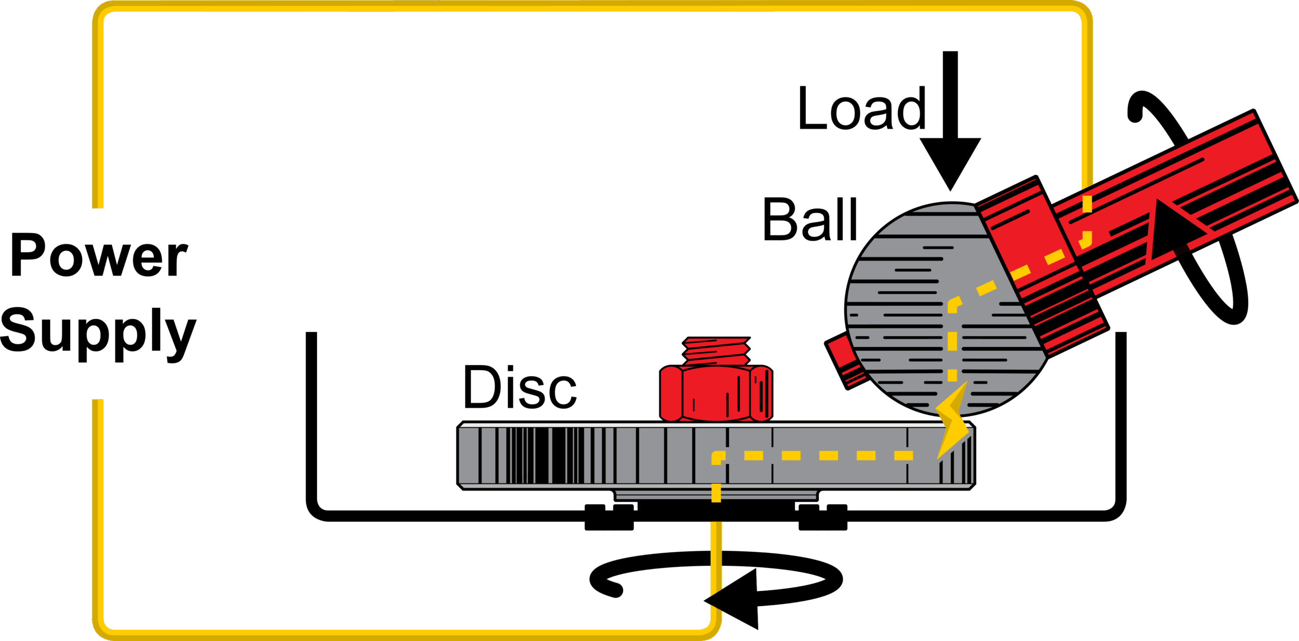
This enables a wide range of test strategies, including tribofilm formation before electrification, tribofilm formation under electrical load, polarity reversal, increasing electrical stress, and comparison of AC and DC conditions.
Different specimen materials and surface coatings can also be investigated where required.
Electrical Conditions
The electrical conditions achievable between the ball and disc are as follows:
Direct Current
- Voltage: Up to 35 V
- Current: Up to 2 Amps
- Ball or disc live
Alternating Current
- Frequency: 0.03 to 500 kHz
- Pk/Pk voltage: Up to 20 V
- Waveform: Sine, Square, triangle, ramp up, ramp down, Sinc, Gaussian, Half sine
The DC current can be controlled with a set current or a set voltage. Balance resistors can also be placed in series with the test circuit to help control current spikes.
Measurement
The principal measurements obtained during ITTM041 testing include:
- Friction
- Tribofilm thickness
- Tribofilm morphology
- Wear
- Surface appearance (by microscopy)
- Applied voltage and current
Tribofilm formation can be monitored using the Spacer Layer Imaging Method (SLIM), allowing changes in film thickness and distribution to be observed throughout the test.
Additional post-test surface analysis can be performed where required.
Example Test Strategies
The interaction between lubricant chemistry and electrified contacts is an emerging area of tribology. As such there is a vast envelope of potential test conditions that can be explored. ITTM041 can be adapted with multiple electrical current options allowing more specific conditions to be studies, and the lubricant response to be rated and understood.
Three example approaches are described below.
Tribofilm Formation Under Electrical Load
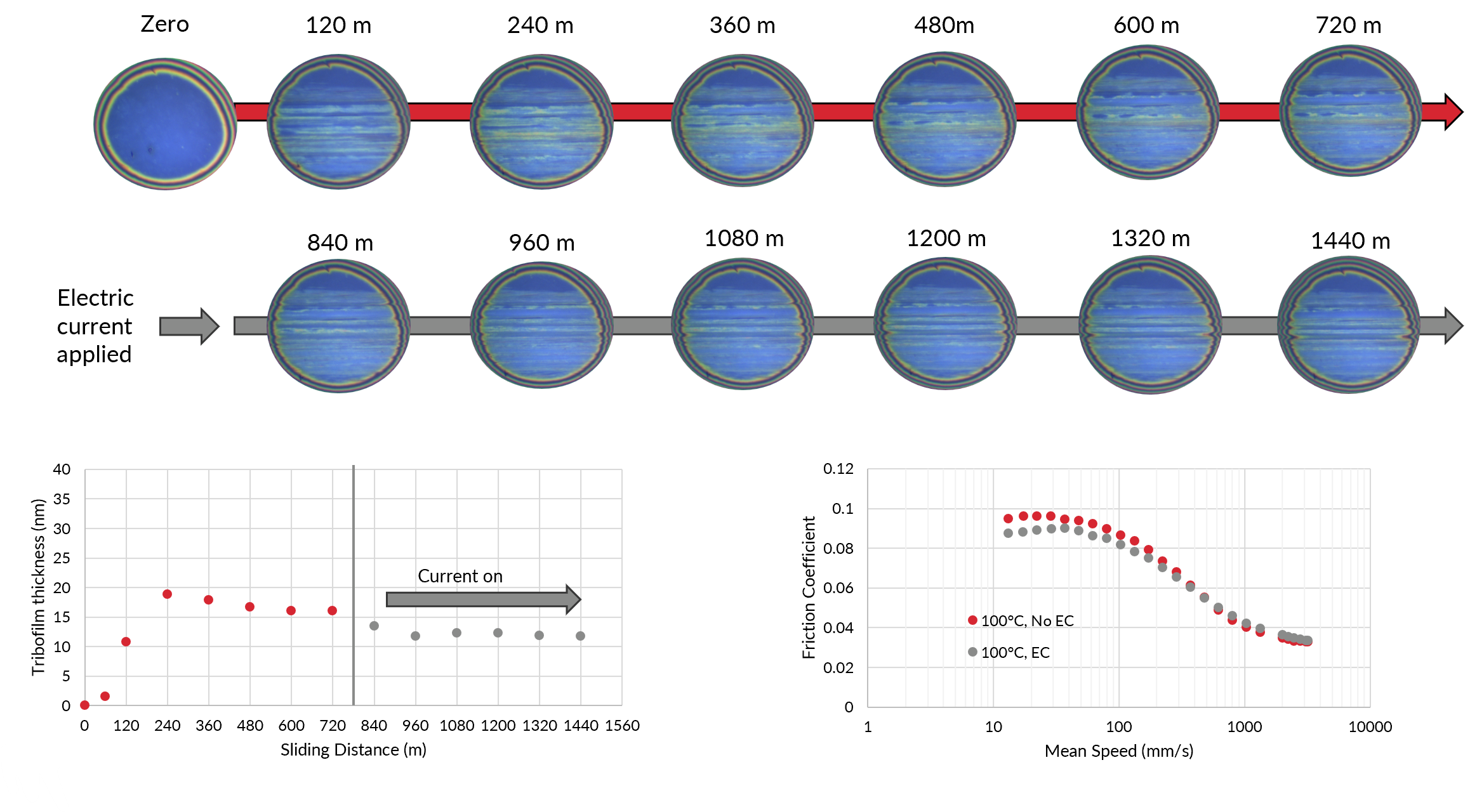
In this study, a tribofilm is initially formed under controlled rolling/sliding conditions without an applied electrical potential. SLIM Images of the ball surface are taken every 120 m of sliding, allowing tribofilm formation to be observed.
Once a stable tribofilm has formed, an electrical potential is applied across the contact and the subsequent change in tribofilm thickness and morphology is monitored.
In the example shown here, a voltage of ~250 mV was used and varied to achieve a set current of 100 mA, with the ball configured as the anode.
Stribeck curves were recorded after the initial 720 m tribofilm-forming stage and again following a further 720 m under electrified conditions. This allows changes in both tribofilm behaviour and friction to be compared.
The results for two different transmission oils are shown in Figure 2 and 3.
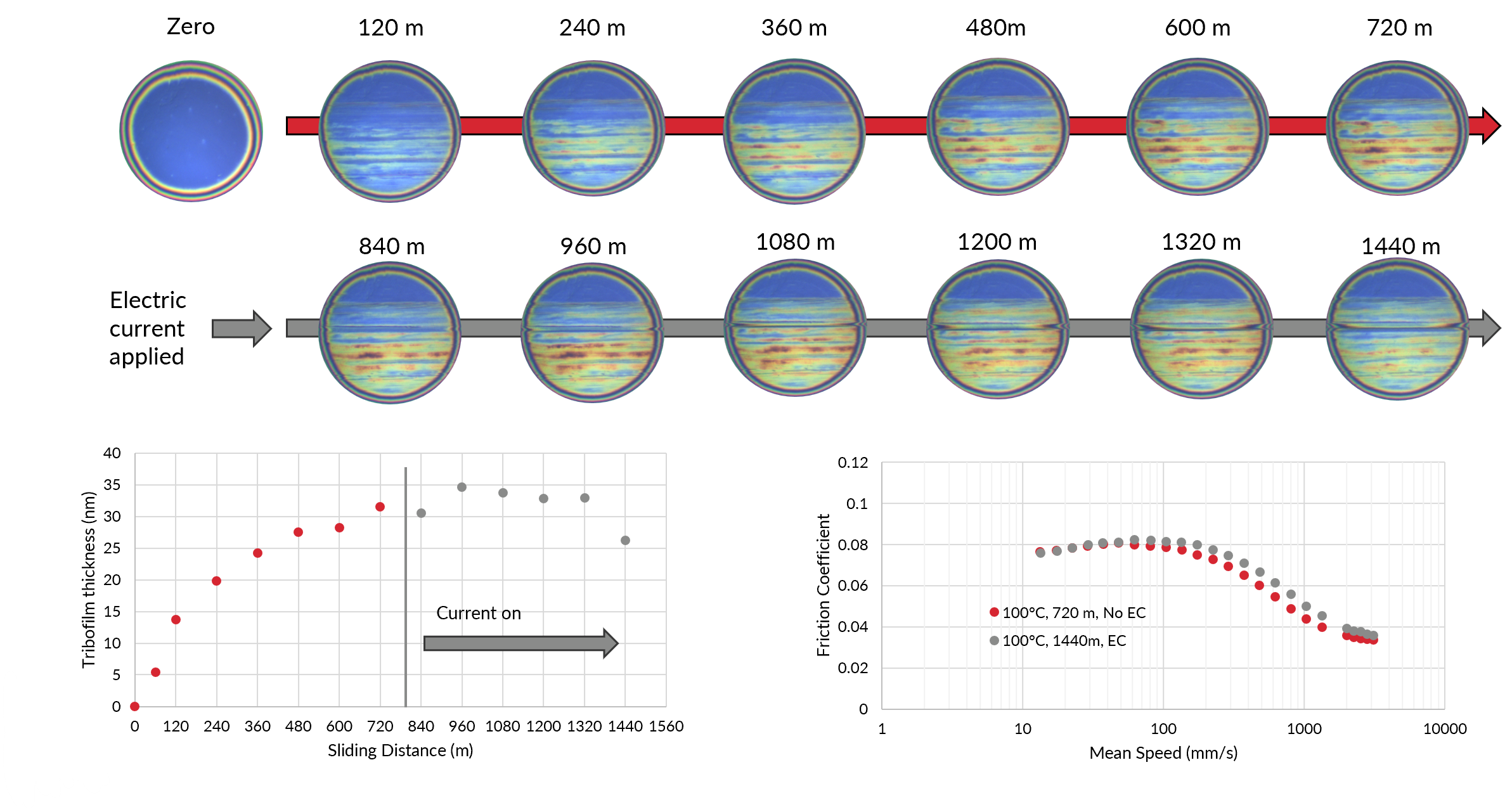
For Oil A, the electrical conditions produced only a relatively small change in measured tribofilm thickness, whilst friction increased slightly within the mixed lubrication regime.
Oil B exhibited a different response. Following electrification, the measured tribofilm thickness decreased and the boundary regime friction was also reduced.
The comparison demonstrates that lubricant formulations can respond differently to otherwise similar electrified contact conditions.
Effect of Voltage Polarity
The nature of the tribofilm (its thickness, morphology and rate of formation) can be effected by the polarity of the applied potential. Here we demonstrate this effect by forming a tribofilm on the ball under three conditions:
- No current
- Ball anodic (100 mA, ~ 250 mV)
- Ball cathodic (100 mA, ~ 250 mV)
The resulting SLIM images are shown in Figure 4.
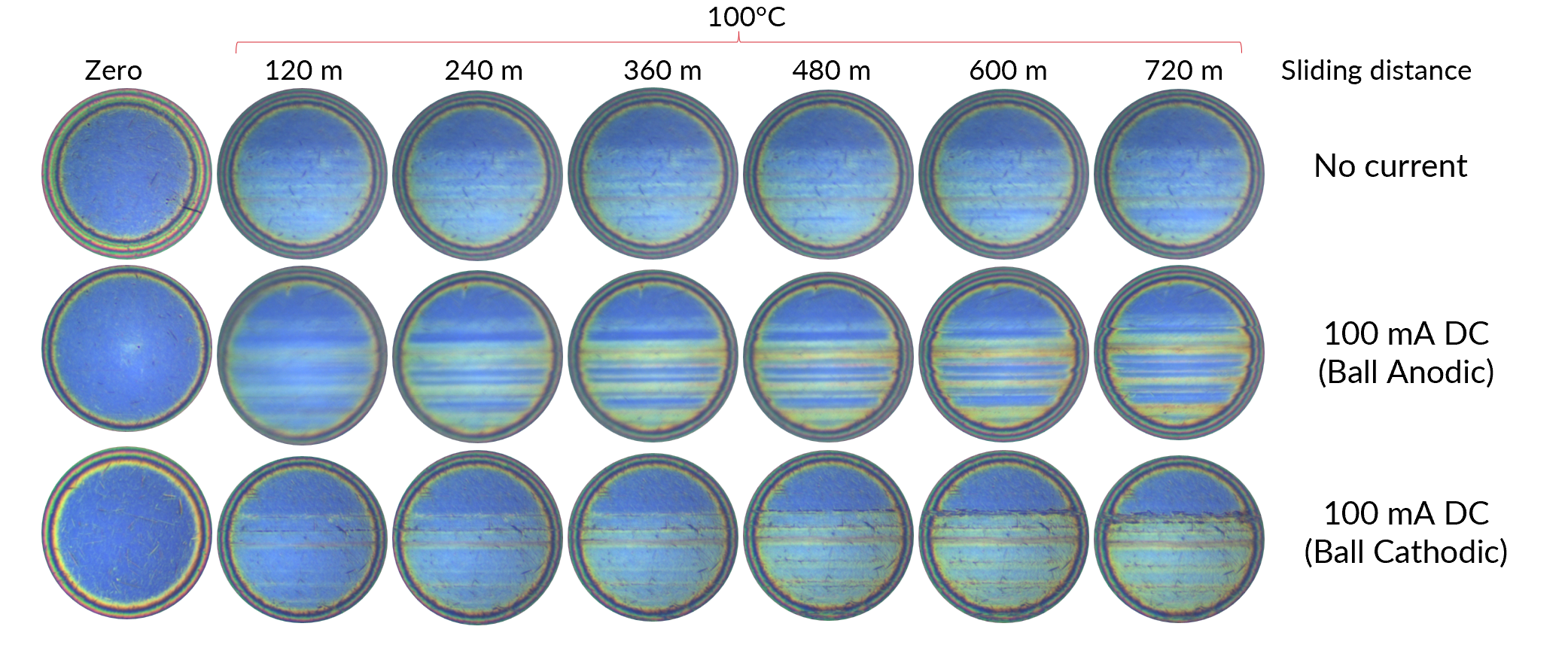
The application of the current increased the observed tribofilm for the oil. The morphology of the Tribofilm was effected by the current, with the ball showing a more varied and stripy tribofilm when in the anodic state.
The variation of the Tribofilm thickness across the ball surface can be measured and is shown in Figure 5.
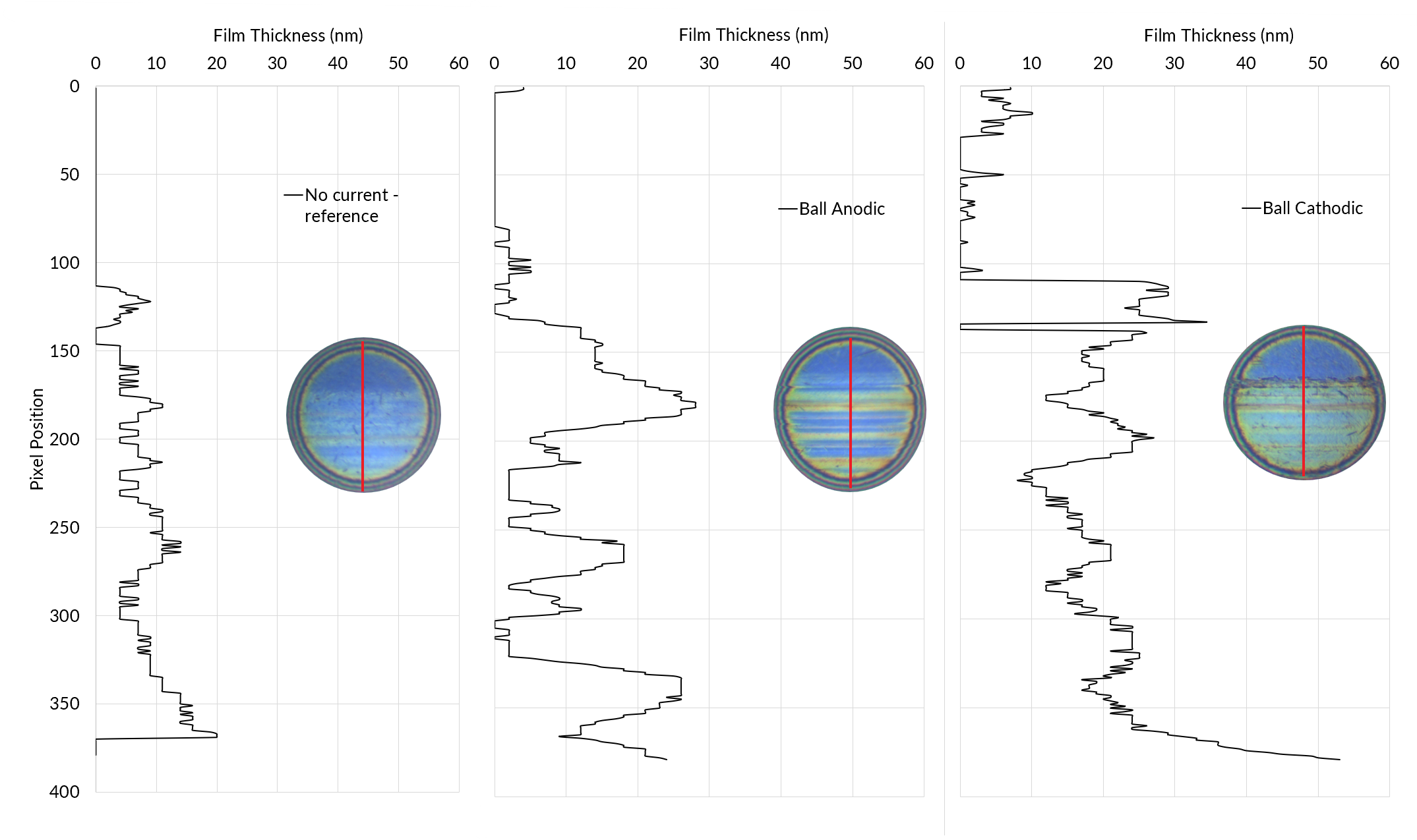
Figure 4 shows the film thickness as measured on the ball surface in the final image of each test. The analysis is taken as a single line vertically in the centre of the ball. When the ball is connected to the positive terminal and is the anode the effect is to increase the thickness of the tribofilm in some areas and to reduce it in others. When the ball is connected to the negative terminal the tribofilm thickness has a general increase compared to the reference. The surface appears fully covered and protected by the tribofilm.
Increasing Electrical Stress and Electrical Discharge Damage
ITTM041 can also be used to investigate the transition from relatively mild electrified-contact conditions towards conditions where electrical discharge damage occurs.
At higher applied voltages the passing electrons can have two effects on the surface: they can enhance the surface tribofilm thickness or cause damage. The damage occurs due to the breakdown of the electrically insulating lubricant film, allowing localised electrical discharge events. This is where the current flashes over from one surface to the other. This can leave pits on the surface, sometimes called frosting or mottling.
The example below compares the same transmission lubricant under different electrical conditions and polarities.
- No EC (reference)
- AC (10V, 20 kHz, current RMS ~ 20 mA)
- 100 mA (~250 mV)
- 1000 mA (~750 mV)
Final SLIM images of the ball surface are shown together with post-test microscopy of the ball and disc.
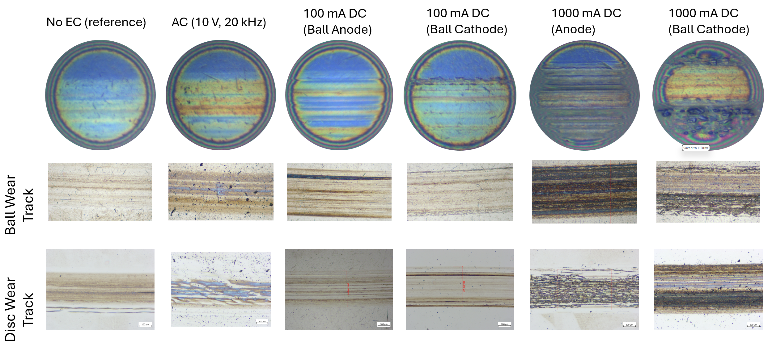
The application of the AC current served to increase the film thickness slightly.
The application of the 100 mA currents has the effect of increasing the tribofilm thickness. At higher currents of 1000 mA, the Tribofilm thickness is increased further, but there is also significant damage caused to the surface.
The image of the surface from the test at 1000 mA DC with ball live is enlarged in Figure 7.
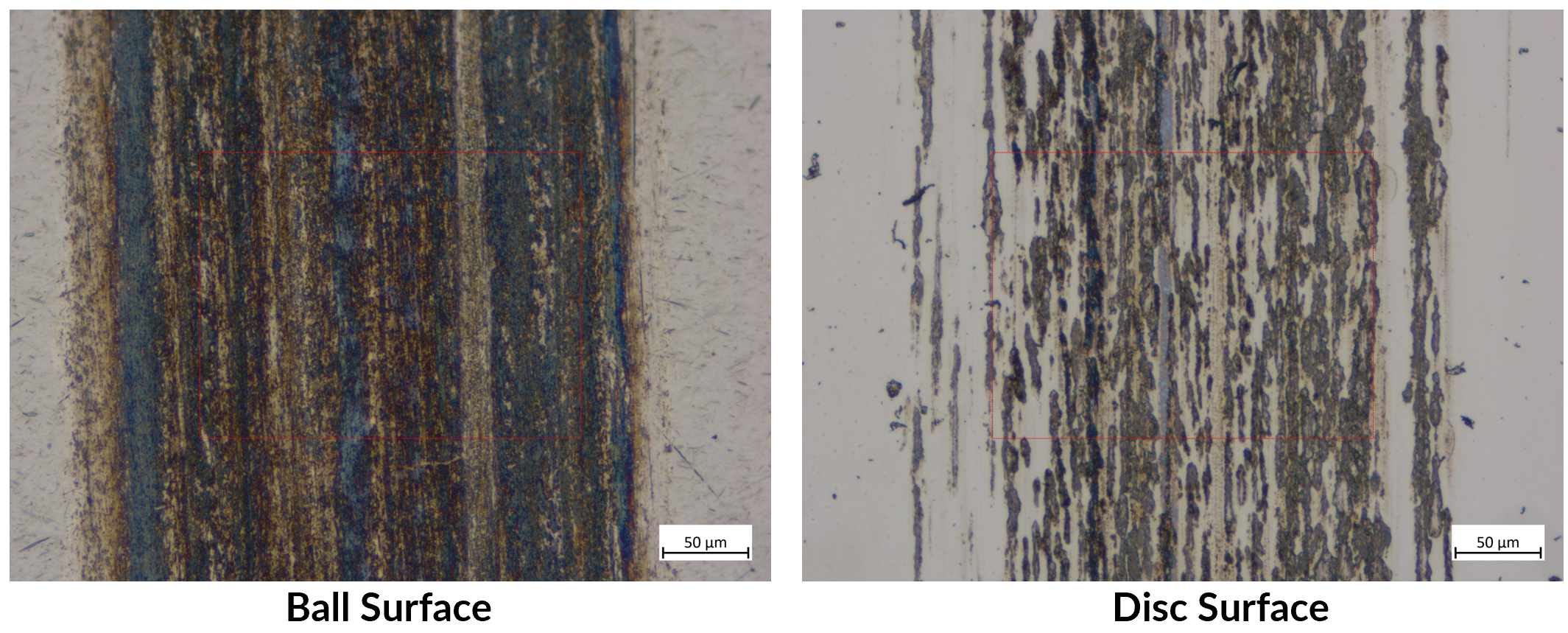
The images show significant build up of a film on the ball surface, intersected with areas of small pits. The disc surface in contrast shows very little visible film, but large discreet pits. These pits are the result of the rapid movement of electrons across the surface, leading to localised melting and surface cracking and pitting.
The corresponding Stribeck curves of the final images from figure 6 are shown in Figure 8.
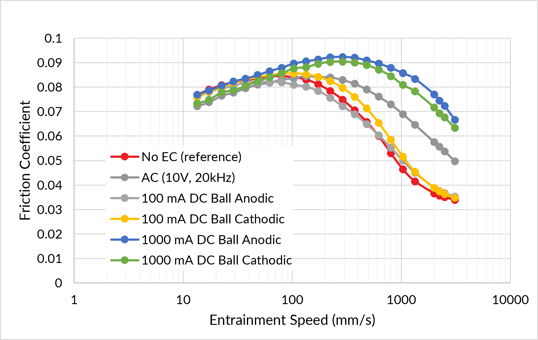
The 1000 mA current has the effect of increasing the friction in the mixed regime, due to the damaged surface increasing the roughness. The application of the AC has the effect of bosting the tribofilm thickness. This has the effect of increasing the mixed friction.
Summary
ITTM041 is used to study the effect of applied electrical current on tribofilm formation, its morphology and the effect on friction. The method can investigate relatively mild electrical conditions, where electrification influences tribofilm formation without substantial surface damage, as well as more severe conditions where electrical discharge damage begins to occur.
DC polarity, AC waveform, voltage, current and mechanical contact conditions can be varied systematically, allowing lubricant formulations and additive technologies to be compared under well-controlled conditions.
ITTM041 can therefore support the development and screening of lubricants and additives intended for electric vehicles, wind turbines, electrified bearings, gear systems and other applications where lubricated contacts may be exposed to electrical potentials and currents.
Additional or linked services:
- Optical Profilometry Quantification of wear, surface roughness, electrical erosion and surface damage.
- SEM / SEM EDX – High-resolution investigation of surface morphology, electrical damage and the elemental composition of tribofilms and deposits.
Book a Test
Testing services can also be booked directly via the Ingram Tribology website: https://ingramtribology.com/request-a-test/
Order code: ITTM041
For more information or to discuss a test programme, please contact: [email protected]
Further Reading
STLE Article on electric vehicles
Yousuf, A., Spikes, H., Guo, L. et al. Influence of Electric Potentials on Surface Damage in Rolling–Sliding Contacts Under Mixed Lubrication. Tribol Lett 73, 45 (2025). https://doi.org/10.1007/s11249-025-01977-2
PCS Instruments Blog article on electrical contacts