

Ingram Tribology Test Method Library
ITTM007 – Last Updated July 2026
Keywords: Wind turbine, gearbox, pitting, spalling, white etching cracks, WECs, eWECs, fatigue, bearings, stray currents
Overview
This method assesses the tendency of wind turbine oil formulation to promote or suppress premature bearing failure associated with White Etching Crack formation, in the presence of electrical currents.
White Etching Cracks, commonly known as WECs, form below the surface of the bearing steel and can lead to the formation of one or more surface spalls and axial cracks. In this method, a controlled electrical current is applied during a rolling/sliding fatigue test to study accelerated WEC behaviour by electrical currents, referred to here as eWEC testing.
This method is designed to compare lubricant formulations under controlled, accelerated test conditions relevant to wind turbine gearbox bearing applications.
Typical Applications
This method is typically used for:
- Wind turbine gear oils
- Industrial gear oils
- Lubricant additive screening
- Investigation of WEC-related premature bearing failure
- Electrified bearing contact studies
Key Benefits
The test provides a controlled and cost-effective way to study the influence of lubricant chemistry on WEC related bearing failure. The test method allows the ranking of different formulations according to the number of contact cycles to failure. It also provides supporting measurements of friction, vibration, surface damage and subsurface microstructural change, for a more in-depth analysis.
The method can help identify lubricant formulations with improved resistance to electrically accelerated pitting failure and can support the development, screening and comparison of wind turbine gear oils.
Test Method
The test consists of three rings running against a central test roller under severe sliding and low lambda ratio conditions. A controlled electrical current is applied throughout the test, to simulate the type of current that may pass through gearbox shaft bearings in wind turbine applications.
The test samples are run under stress until a surface pit is formed, or the test reaches a pre-defined run-out.
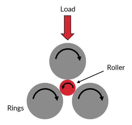
Applied Current
An electrical current is applied between the ring and the roller. The voltage and the current are controlled and measured throughout the testing. Ensuring accuracy, consistency and field relevance of the tests.
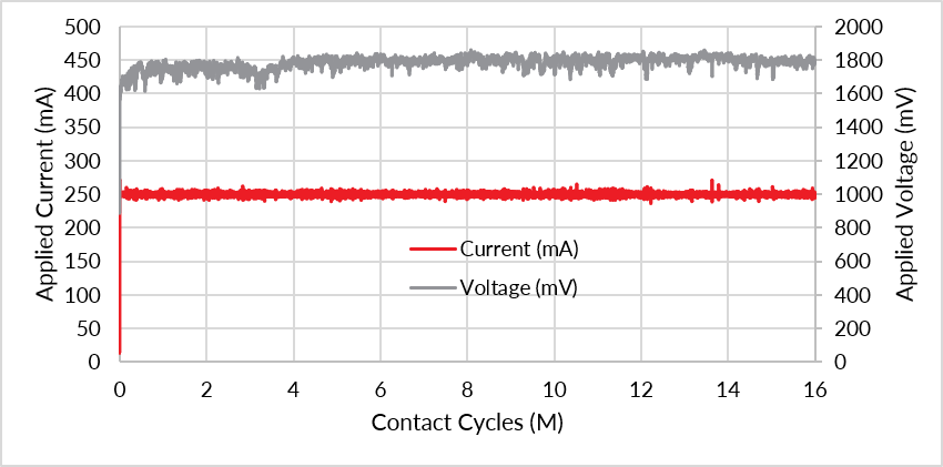
Figure 1: Example trace showing the control of the electrical current during the progression of the fatigue test
Measurement
The main test outputs are:
- Contact cycles to failure
- Microscopy images of the pitted or damaged area
- Friction coefficient
- Vibration response
- Subsurface analysis of the test roller
Together, these measurements allow lubricant performance to be ranked and provide insight into the mechanisms controlling WEC formation.
Subsurface analysis is conducted on the end of test roller, to confirm the presence of white etching crack networks below the surface.
Example Test Output
The example test results below compare two reference oils:
- Reference Oil A: low-performing reference oil
- Reference Oil B: high-performing reference oil
WEC Progression
The friction and the vibration are monitored throughout the test. A sharp increase in vibration is indicative of the formation of a pit. A consistently low vibration response suggest that the contact remains relatively stable, with little or no surface damage.
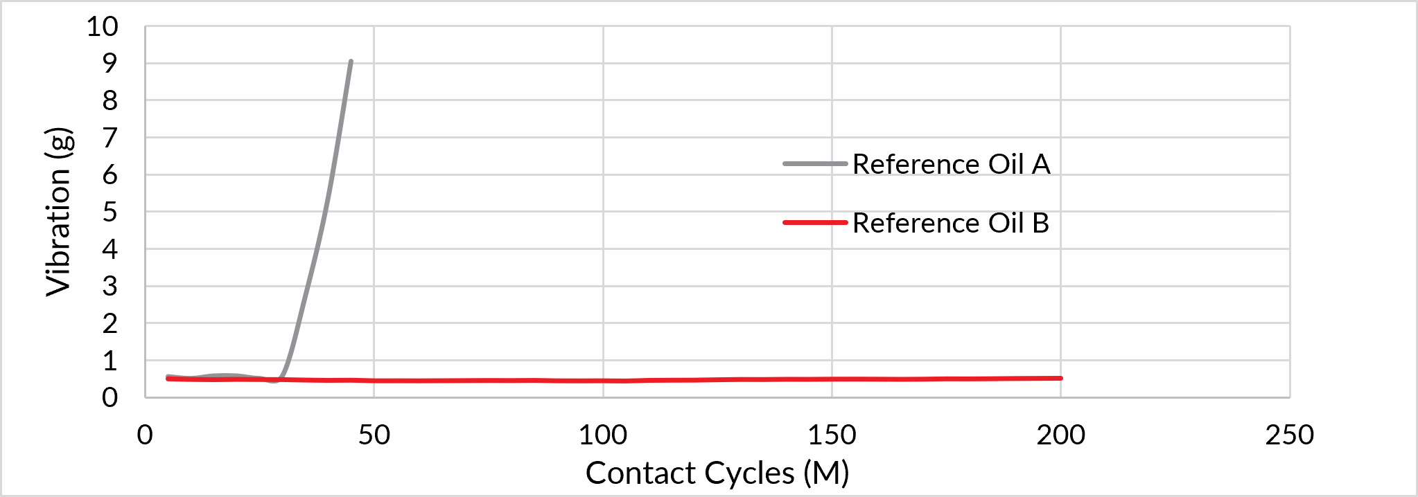
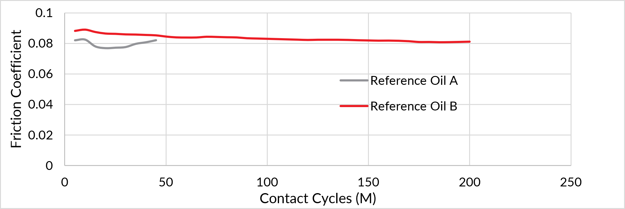
Figure 2: Example Vibration and Friction measurements during the eWEC test
Pitted Surfaces
At the end of the test, the surface of the test roller is inspected for the presence of subsurface-initiated pits and axial cracks, which are indicative of WEC formation.
The example images shown in Figure 3 compare the surface of the test roller after testing with Reference Oil A and B. Reference Oil A produced a large spall, while Reference Oil B produced very little damage, with only small pits observed.
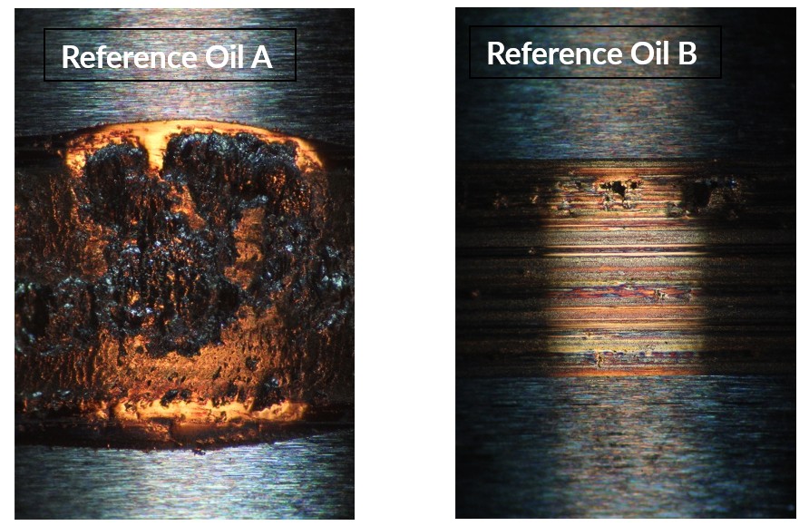
Figure 3: Example surface images from testing with Reference Oil A (left) and B (right)
Subsurface
The subsurface of the roller is investigated for metallurgical changes associated with WEC-related fatigue. This can include:
- White Etching Cracks
- White Etching Areas
- Dark Etching Areas
- Inclusions
- Butterfly features
Some example images from this analysis is shown in Figure 4 and 5. The test with Reference Oil A showed multiple regions containing WEC networks. The roller tested with Reference Oil B showed no changes to the steel, and no WEC-related features were found in the analysed sections.
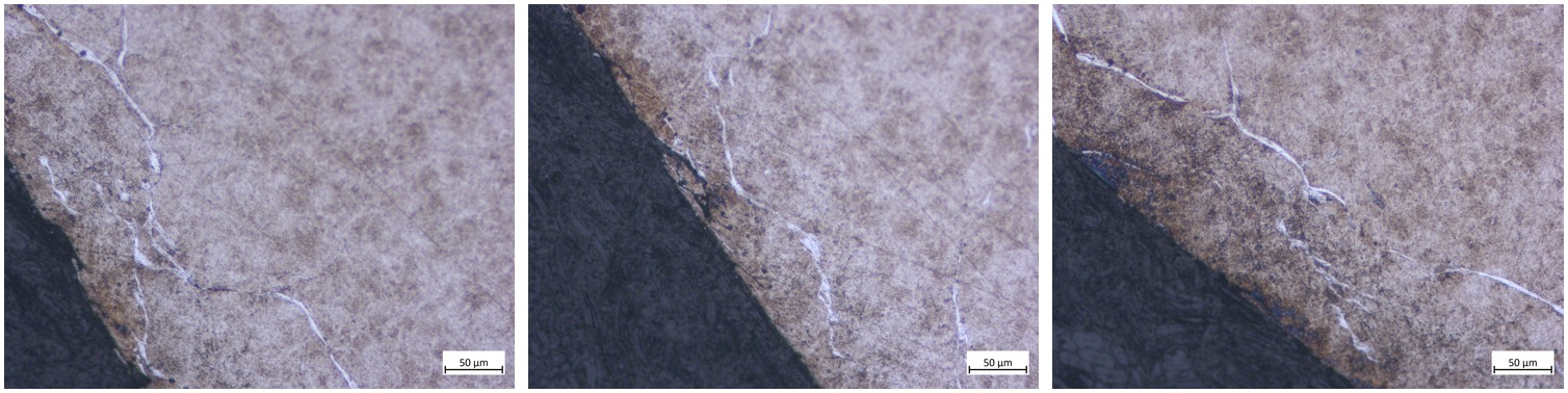
Figure 4: Example microscope images of the subsurface of the roller, showing white etching crack networks formed by Reference Oil A
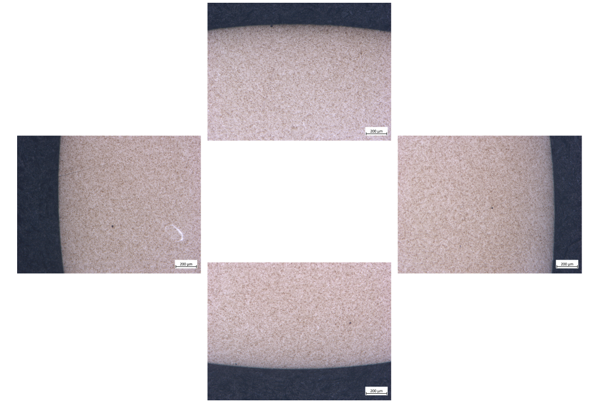
Figure 5: Example microscope images of the subsurface of the roller, showing a pristine material after testing with Reference Oil B
Summary
The eWEC test method is used to quickly and accurately compare lubricant formulations intended for wind turbine gearbox applications. Assessing the lubricants tendency to promote or suppress the formation of WEC induced pitting in the presence of stray electrical currents.
Additional or linked services:
This method can be combined with additional surface and failure analysis techniques, including:
- ITTM041 – Electrified tribofilm study
- SEM / SEM-EDX
Book a Test
Testing services can also be booked directly via the Ingram Tribology website: https://ingramtribology.com/request-a-test/
Order code: ITTM007
For more information or to discuss a test programme, please contact: [email protected]